Airlines and aircraft manufacturers are constantly striving to design aircraft that are more in line with the climate goals. All of these innovative new designs need to be extensively analysed and tested for such matters as efficiency, safety and noise, and also to ensure compliance with the aviation sector’s stringent requirements and certification procedures. “The more test data an aircraft manufacturer can obtain from a wind tunnel test the better it is, and that is precisely why manufacturers turn to Royal NLR: building complex wind tunnel models in a short space of time”, says Jan Scholten, Engineering & Technical Services Manager.
Sensors, rotating engines, moving flaps, 900 static pressure holes, and more
NLR has specialised in smart wind tunnel models in recent years. The models may consist of a combination of numerous different built-in sensors, rotating engines and moving flaps. Scholten mentions as an example a wind tunnel model that NLR uses to test take-off and landing positions. Such a model can easily have 800 to 900 static pressure holes for measuring pressure. By adding dynamic pressure holes, it is possible to simultaneously measure the turbulence across the tail sections caused by the wings when the aircraft takes off. “Many other builders of wind tunnel models lack in-house expertise to make a functional test instrument of a model or to combine test requirements in such a way that you need only one model. We aim to be the global leader in this field.”
From an engineering point of view, there are similar knowledge institutes in Europe. “The difference that NLR makes compared with those institutes is that we are more commercial in our thinking and start to work in parallel even at the design stage”, says Scholten. “NLR has in-house all the disciplines such as aerospace systems and operations that are needed to develop a complex wind tunnel model. And if necessary, we work overtime, including weekends to assure we are on time for the wind tunnel test.”

NLR engineering workshop in Flevoland
Craftsmanship
Alongside the state-of-the-art machines there are some old, indestructible and occasionally indispensable milling machines, all maintained with equal love and dedication. For the high-end precision work, the CNC machining area is climate conditioned. This ensures the accurate manufacturing for the entire range of parts required, ranging from very small dimensions to double curvature parts up to 3 meters length. Next to this, there is an instrumentation and an assembly area where an employee with a sharp eye for precision fits very small parts, all done by hand, explains Scholten during a guided tour.
Next to the design room, where new designs supplied by aircraft manufacturers are transformed into designs of wind tunnel models, work is performed using new materials and electronic components like: composites, 3D-printed parts in plastic and various metals, and specially-made printed circuit boards and other electronics. Developments that occur here will lead in the future to new possibilities for designing and making highly-advanced wind tunnel models, at the boundary of what is technically feasible. All of this is being done for the purpose of the tests that an aircraft manufacturer wants to be able to perform.
Real-time wireless measurement techniques: gigabytes per second
Traditionally, a sliding contact has always been used for data transfer involving moving parts in complex wind tunnel models. But the big disadvantage of a sliding contact is that the maximum amount of data transferable real-time is fairly small. Using completely wireless techniques, it is possible to transfer both data and power to perform measurements on rotating and moving parts of things like engines and propellers, for which NLR even holds a patent. Scholten: “You can transfer far less data with a sliding contact. With the digital wireless method, we can achieve enormous speeds and transfer gigabytes per second.”
Short lead time
“While costs are an important matter for aircraft manufacturers, the decisive factor is increasingly becoming a short lead time”, says Scholten. “At NLR we can confidently give a date for when a wind tunnel model will be finished, which is something at least equally important to an aircraft manufacturer, particularly because the manufacturer cannot proceed with its design if the calculations have not yet been tested in a wind tunnel model.”
By working in parallel in the design and manufacturing phase of a wind tunnel model, NLR is able to move faster than similar institutes. Scholten explains that right from the start the design of a typical wind tunnel model for take-off and landing tests is divided up into four or five different parts. So NLR assigns four or five designers to do the work. For example, somebody will work specifically on the landing gear or only on the wings or the tail. “This enables NLR to complete a design four or five times faster than is customary with sequential design. We are capable of building a wind tunnel model for take-off and landing conditions in 22 to 23 weeks, and sometimes even sooner.”
The combination of engineering capabilities and speed has given NLR an edge. “We already begin milling parts before the design has been finished”, says Scholten. “If you know roughly how large a wing will be, you can already start up the milling cutter. The exact details will follow later, but by then the large bits and pieces will already be ready.”
Wind tunnel models made from steel, composites, plastic and 3D metal printing
NLR is conducting a lot of experiments with different composites. This gives NLR a big advantage and it assures that there is the possibility to build complex wind tunnel models using composites, plastic, steel, 3D metal-printed parts and combinations thereof. For this purpose, NLR can draw on the expertise within its own organisation for such matters as structures technology for composites, flight physics for CFD computation, collaborative engineering for finite element modelling, electronics and data transmission and processing.
Scholten mentions an example of a printed wingtip with a huge number of pressure holes with internally printed ducts. “With the traditional method, you would have to install a whole load of separate tubes in the model. There comes a time when you can’t go any further. So it’s physically impossible. That’s why we had the ducts printed in 3D in the model so as to retain strength”, says Scholten.
Military transport aircraft KC390
Depending on the type of wind tunnel model, the wind tunnel model becomes increasingly detailed as the process moves forward. By way of example, Scholten mentions the KC390, a military transport aircraft under a European call for tenders. After the initial design was carried out as a wind tunnel model, it transpired that minor alterations were necessary to obtain better properties. The real refining of a model like the KC390 occurs at the end. What made the aircraft special was that it had to be capable of refuelling other aircraft in the air and also of dropping parachutes.
Scholten: “Rolling out the fuel line is quite a job in itself and nobody wants it to be blown away because of a vortex behind the aircraft, and parachutes are not easy either because they can be sucked back and hit the fuselage or the tail.”
NICETRIP
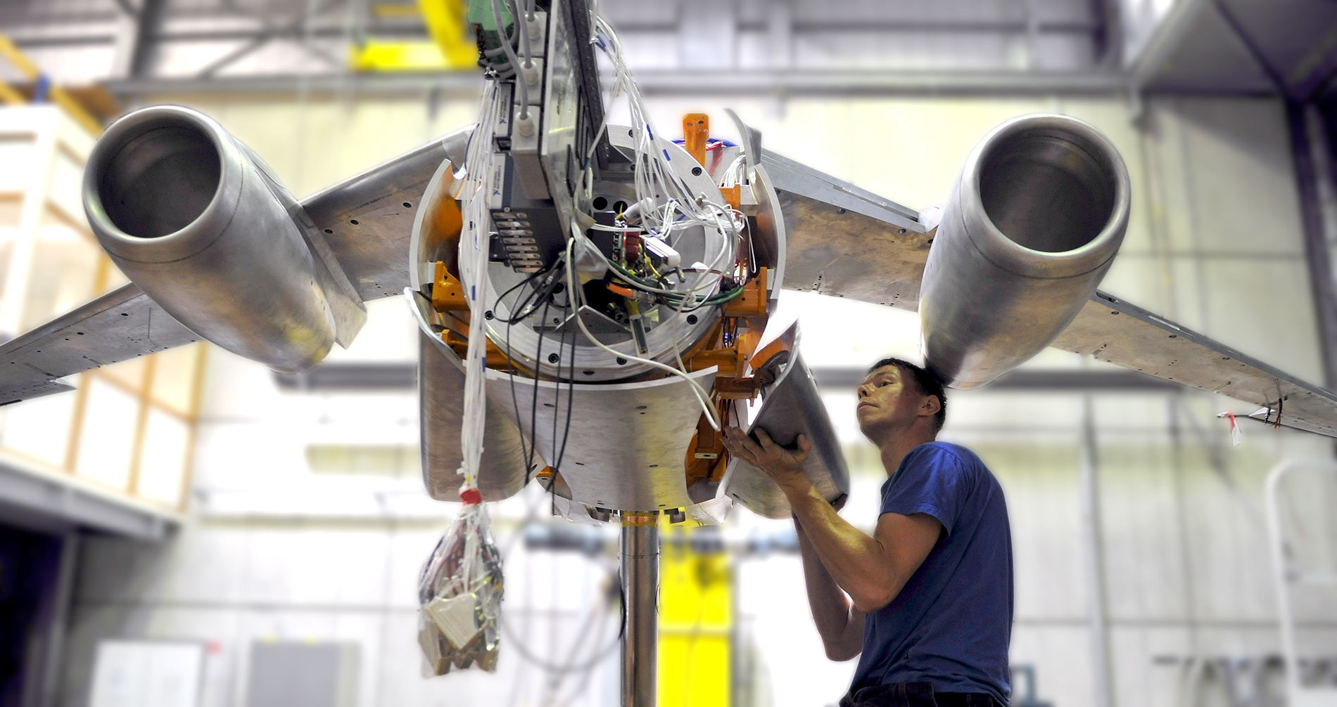
A smart wind tunnel model of NICETRIP, a European military aircraft also capable of vertical take-off by means of rotatable propellers, presented a challenge because both the wings and the engines had to be able to tilt (European tiltrotor). This was a combination of air propulsion for the engine and propeller and propulsion for the flaps and wings that also had to be settable to the vertical position. The model was then provided with numerous sensors that had to be capable of accurately measuring the lateral forces and moments, including those on the propellers.
“The complexity of the NICETRIP project was very high”, says Michele Arra, Head of Research and Innovation from the Leonardo Company in Italy, the programme coordinator . “Part of this complexity was the possibility to have a fully functional wind tunnel model of a significant size to validate the architecture and the conceptual design for a future tiltrotor. The design and development of such a wind tunnel model was where the outstanding NLR capabilities and expertise came in.”
The ultimate wind tunnel model
Over the past years, Scholten has made many advanced wind tunnel models. But what does Scholten consider the most interesting or finest project that he has worked on? “The Ariane rocket!”, he proclaims. “It’s every boy’s dream. A rocket like that, it’s something you seldom do. So if you get a chance to work on it… It’s what everybody wants. Really special.”
Wind tunnels within walking distance: DNW
NLR’s site in Flevoland province has a very favourable location. Besides possessing a range of research infrastructures, the site houses two internationally acclaimed wind tunnels of DNW, the joint venture between NLR and Germany’s DLR. So it’s hardly surprising that NLR has a complete workshop at this location with multiple high-end five-axle milling machines and other machinery for building wind tunnel models. Scholten: “It’s obviously very handy if testing is done at DNW for us to be within walking distance if we made the wind tunnel model for testing. There is immediate feedback about use of models. It allows us to produce a better model because just around the corner we get feedback from the tunnel.”