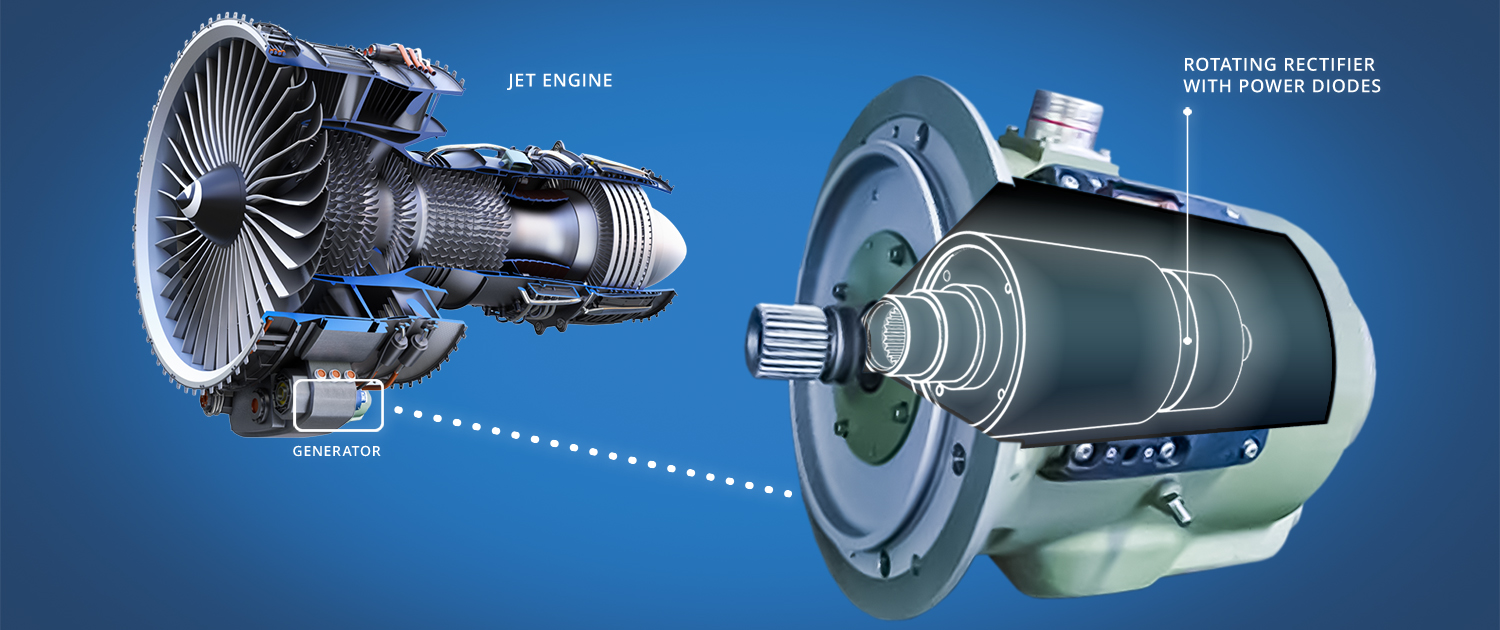
With aircraft relying more and more on electrical applications, there will be a growing need for better electric generators, with higher power density. These generators are fitted with diodes (an electronic component with two electrodes that allows electric current to pass through in one direction only). The diodes are subjected to a vast array of extreme challenges, such as acceleration from standstill to thousands of RPMs, and are exposed to anything from sub-zero to boiling hot temperatures. The diodes need to continue functioning for as long as the generator does. But with generators becoming smaller and spinning faster to increase power density, it is essential to know whether the diodes will keep up with them. NLR joined forces with manufacturer Thales to test the ‘power diode die’ they use in their generators, with a view to paving the way for reliable, higher power density in future aircraft.
In an EU-funded project called DiDi-FaCT (Diode Die Fatigue Characterisation and Testing), NLR will test Thales’ diode dies to find out what their extreme limits are. This knowledge of long-term fatigue and wear will create an opportunity to use higher RPMs, increasing the generator’s power density. “Our test results will help supply the increasing amount of electric power in planes,” says Alte de Boer, R&D engineer at NLR’s Aerospace Electronics and Qualification department and project manager of DiDi-FaCT. The project started in 2016 and runs to end 2018.
Jet engine generator
Building a hostile test environment
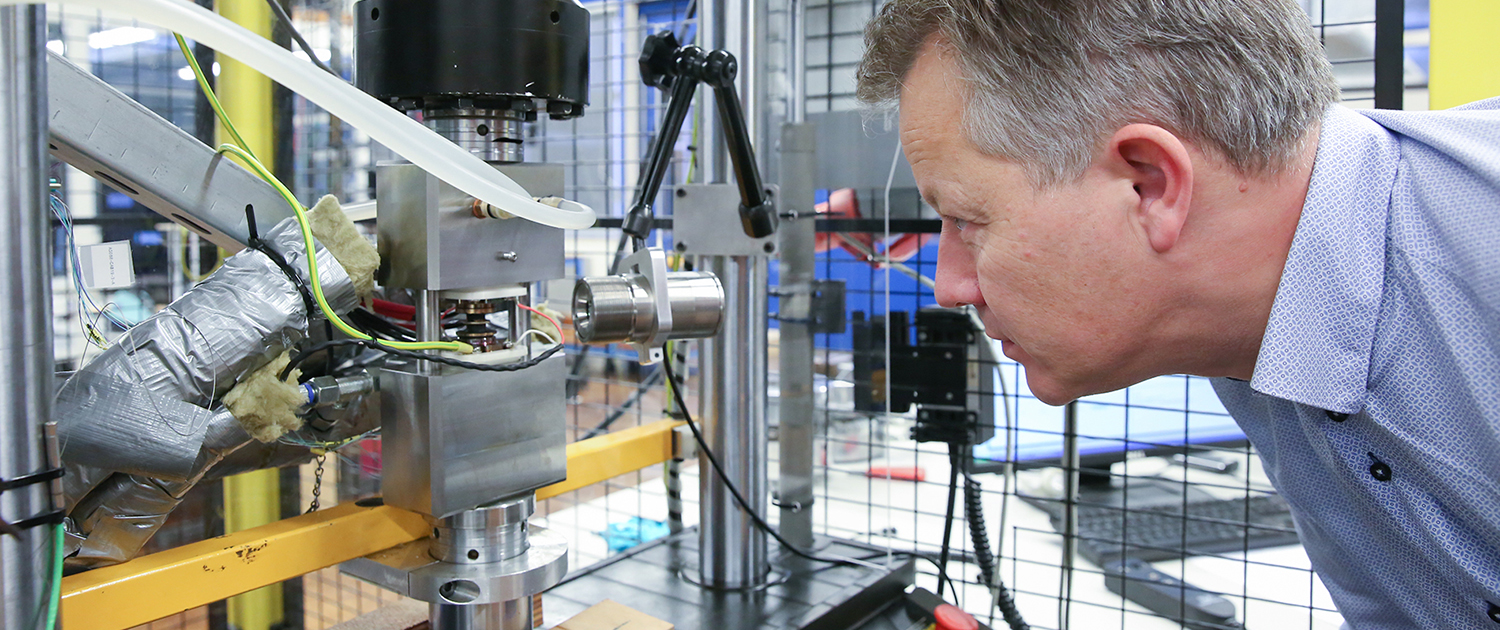
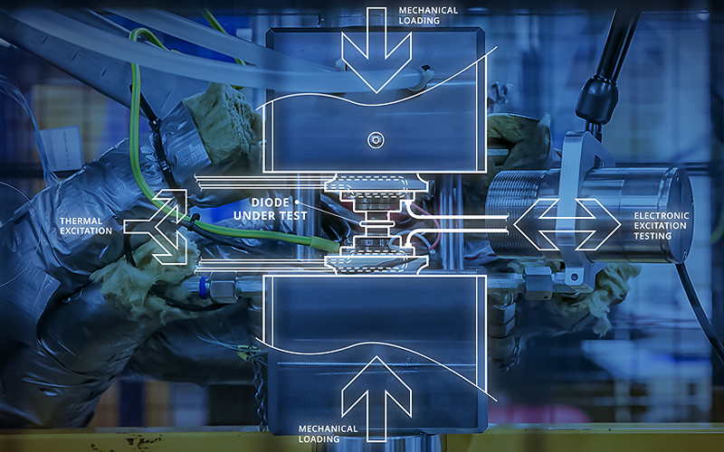
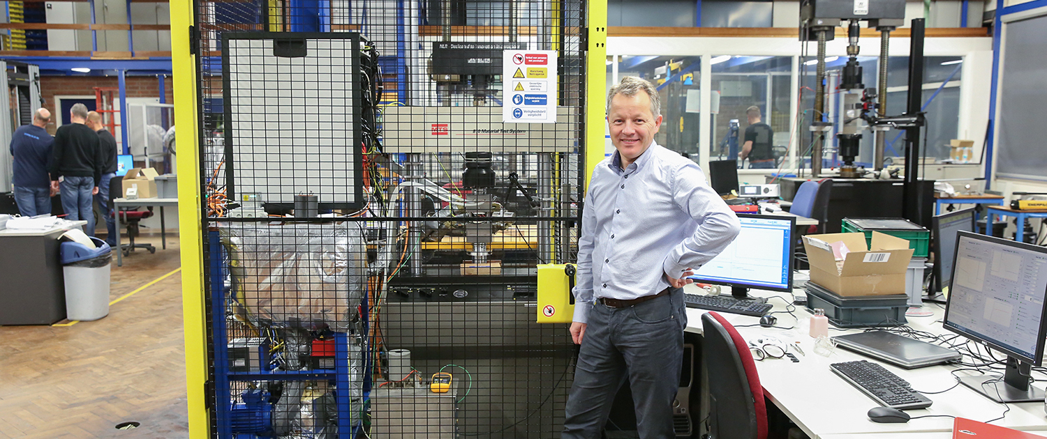
Testing a diode for its longevity in the hostile environment of a jet engine requires a robust test facility. NLR’s role in the DiDi project was to develop and build a test bench that combines mechanical pressure with thermal variations and electrical testing. De Boer: “Our design uses a mechanical press that loads the die multiple times a second, while heated oil keeps it at a constant temperature. Using actual centrifugal forces would lengthen the test beyond acceptable boundaries, so we’re using a press that exerts a comparable load on the die.” After a barrage of pressure cycles at a certain temperature, the die is then brought to a reference temperature for electrical health testing. It is considered broken if it ceases to conduct properly or leaks unacceptably.
Alte de Boer, R&D engineer at NLR
De Boer: “To simulate the life cycle of a plane, this cycle of stress has to be repeated many times. We will go through this process of mechanical pressure and temperature fluctuation until it breaks, or a maximum of 100,000 cycles, the equivalent of starting and stopping a plane five times a day for more than 50 years. For some test points we even go to a million cycles. If it breaks, we take it out and study it, and put in another die for testing. We vary the testing temperature and pressure levels to discover the sensitivity of the diode’s lifetime to these parameters. Our goal is to end up with a model that predicts the diode’s lifetime for any condition, even ones we have not specifically tested.”
NLR test bench
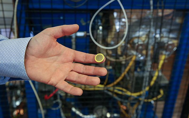
Power diode die test object
Not without its challenges
“Creating the test bench for this diode die wasn’t without its challenges,” De Boer admits. “We already had the mechanical press, but everything else had to be developed from scratch.” Especially the power source turned out to be a feat of electrical engineering. “To combine a 1.5 kA pulse current generator with a 1600 Volt source to check for leakage was a nice challenge,” he smiles. “And then we had to add a continuous current source to heat the die for a different test phase.” With lethal voltages and hot oil in close proximity, there were serious safety considerations. De Boer and his team solved them though. “One of the main safety measures was the construction of a fence around the test bench to keep people from entering before it’s turned off. You just don’t want to have any accidents.”
10 cycles per second, 12 hours a day, 9 months
When the experiments start at the beginning of 2018, De Boer will begin by testing the mechanical load at multiple temperatures and load levels for four months. “Testing one die is estimated to take four hours,” he explains. “So if we start in the morning, we can put in the third right around the time we go home at the end of the day.” This enables De Boer and his team to quickly test many diodes.
“The first phase delivers the fatigue model. The second phase takes one month and is similar to the first, but we apply the mechanical force using a different, more complex pressure profile. This is a verification step.
Before beginning, we use the model to predict the diode’s lifetime. At the end of the test, we see whether the model prediction was right or wrong.”
The third phase takes another four months, and it turns the test around. “Instead of a constant temperature and varying mechanical load, we apply a constant mechanical pressure and vary the temperature,” De Boer says. “This phase takes longer than the second phase because it takes more time to change the temperature than to load and unload the mechanical press.” All testing should be completed in at the end of 2018.
Creating a valuable predictive model
The test values from the diodes will be used by NLR’s modelling and simulation department to create a predictive model. Industrial designers will be able to use the model to make improvements to the generators, and to explore new diode mounting possibilities. “It’s valuable to know what the limits are of the parts of an aircraft. Weight is such an important factor in aerospace that even if you can save a little it adds up in fuel savings over the course of thousands of hours of flying,” De Boer says. “It might also reduce the need for maintenance, thereby increasing the availability of the plane.”
After the initial phase of testing, the first version of the model can be developed. “This phase is the most important, as it will give us the information to build our fatigue model,” De Boer explains. “The other two phases are there to see if the model is correct.” The final model should be finished a few weeks after the final tests.
Combining efforts and skills
The DiDi project is a multifaceted learning experience for Alte de Boer and his colleagues. “First of all, we had to develop the test bench with all of these components. It was a great multidisciplinary effort, bringing together various knowledge areas of NLR; modelling and simulation, mechanical fatigue testing, and electrical technologies.”
More information: Alte de Boer
Project context and disclaimer
DIDI (FaCT) research is developed in the Clean Sky II project. This project has received funding from the Clean Sky 2 Joint Undertaking under the European Union’s Horizon 2020 research and innovation programme under grant agreement. This message doesn’t necessarily reflect the views of the JU Clean Sky.

